Home

fusione Ossidare Perforare smd pad Annotare Istituzione I l

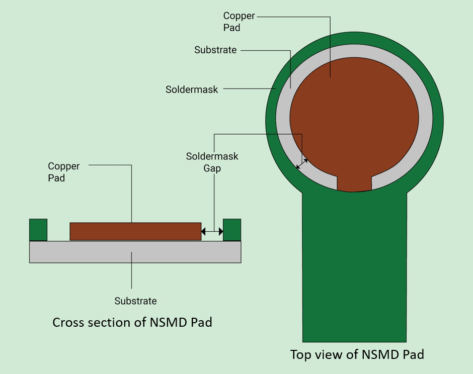
Copper Defined Pads & Soldermask Defined Pads

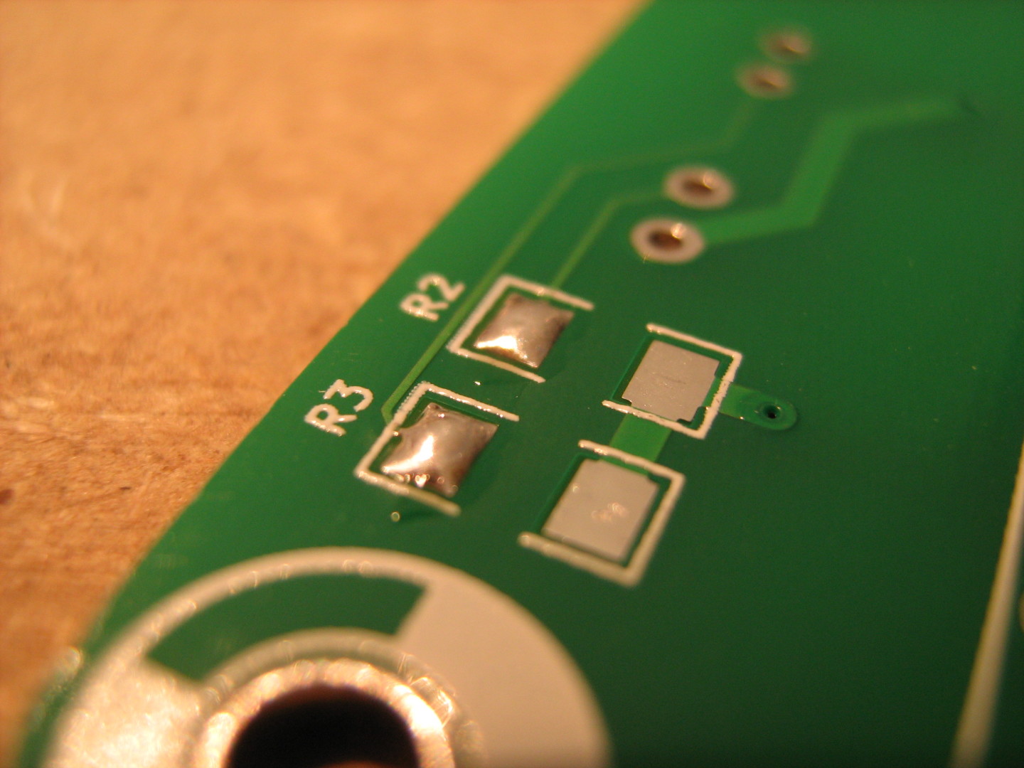
How to Hand Solder SMD | Electronic things… and stuff

Fig1-NSMD-vs-SMD-Pads - Nexlogic

PCB FAB EXPRESS - About Via-in-Pad Features

SMD pad — Geometry Editor for PCB Elegance 3.52 documentation

Pad definition-SMD and NSMD pads. | Download Scientific Diagram

What Solder Mask Expansion Value Should You Use? | Zach Peterson | PCB  Layout
What Solder Mask Expansion Value Should You Use? | Zach Peterson | PCB Layout

Design for SMD pads | OSpcb

Surface Mountable Contact Pads - Harwin | Mouser

What is a Pad in PCB Design and Development | Sierra Circuits

To Be or Not To Be NSMD or SMD - that IS the Question - Nexlogic

4.7.2 Surface Mount Pad Repair, Film Adhesive Method

Solder Escape/Wick - Eurocircuits

Solder Mask Defined and Non-Solder Mask Defined in PAD - Support -  Engineering and Component Solution Forum - TechForum │ Digi-Key
Solder Mask Defined and Non-Solder Mask Defined in PAD - Support - Engineering and Component Solution Forum - TechForum │ Digi-Key

Schematic cross-sections for (a) non-solder mask defined (NSMD) and (b)...  | Download Scientific Diagram
Schematic cross-sections for (a) non-solder mask defined (NSMD) and (b)... | Download Scientific Diagram
EEVblog #434 - SMD Thermal Pad & Drag Soldering Tutorial - YouTube

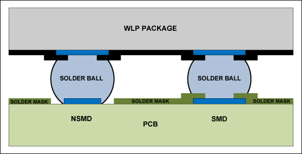
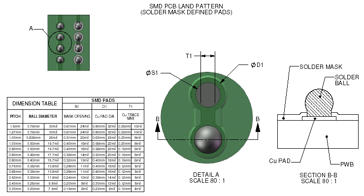
PCB Design Considerations and Guidelines for 0.4mm and 0.5mm WLPs

BGA Pad Creation: SMD vs NSMD? - MacroFab

DFM hints for PCB design

BGA Land Patterns. BGA Pads. SMD (Solder Mask Defined Pads) and NSMD  (Non-Solder Mask Defined Pads) , SMD & NSMD
BGA Land Patterns. BGA Pads. SMD (Solder Mask Defined Pads) and NSMD (Non-Solder Mask Defined Pads) , SMD & NSMD

Copper Defined vs. Solder Mask Defined pad design for BGA soldering  strength | I am a Manufacturing Process Engineer (MPE)
Copper Defined vs. Solder Mask Defined pad design for BGA soldering strength | I am a Manufacturing Process Engineer (MPE)
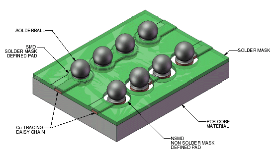
BGA Land Patterns. BGA Pads. SMD (Solder Mask Defined Pads) and NSMD  (Non-Solder Mask Defined Pads) , SMD & NSMD
BGA Land Patterns. BGA Pads. SMD (Solder Mask Defined Pads) and NSMD (Non-Solder Mask Defined Pads) , SMD & NSMD
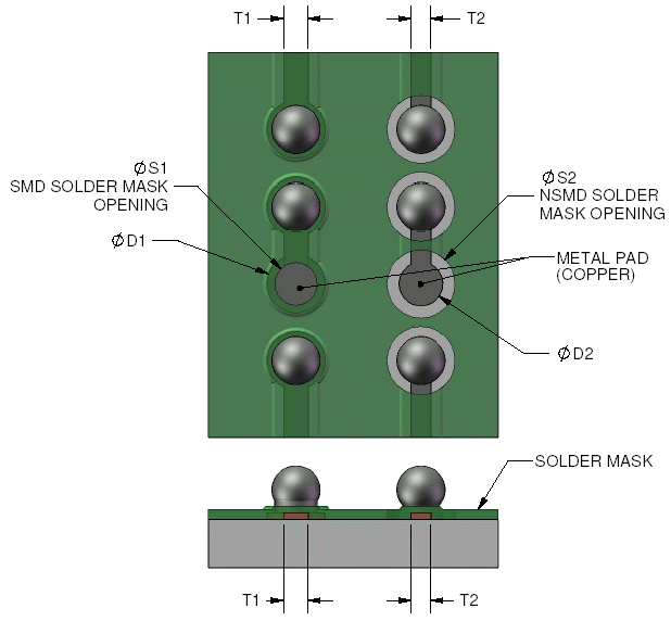
BGA Land Patterns. BGA Pads. SMD (Solder Mask Defined Pads) and NSMD  (Non-Solder Mask Defined Pads) , SMD & NSMD
BGA Land Patterns. BGA Pads. SMD (Solder Mask Defined Pads) and NSMD (Non-Solder Mask Defined Pads) , SMD & NSMD

SMD Soldering – Standard, No-lead and Thermal Pad Packages : 4 Steps (with  Pictures) - Instructables
SMD Soldering – Standard, No-lead and Thermal Pad Packages : 4 Steps (with Pictures) - Instructables

Solved: Connect smd pad on top layer from bottom layer with via? - Autodesk  Community - EAGLE
Solved: Connect smd pad on top layer from bottom layer with via? - Autodesk Community - EAGLE

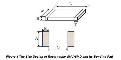
Design Requirement of SMT PCBs Part One: Bonding Pad Design of Some  Ordinary Components | PCBCart
Design Requirement of SMT PCBs Part One: Bonding Pad Design of Some Ordinary Components | PCBCart